4 Channel Active Sound Filter Schema Adjustable Frequency
A 4-way active filter scheme is presented here with the particularity of using only easy-to-find components: op amps, potentiometers, resistors and capacitors.
Here is a 4 channel active filter scheme with adjustable transition frequencies. For multi-amplification, an active filter is essential to distribute the frequency bands for their respective amps and speakers. Here is presented a 4-way active filter. It is possible to modify it according to what one wishes to realize as acoustic system (sound system).
Active sound filter: the diagram
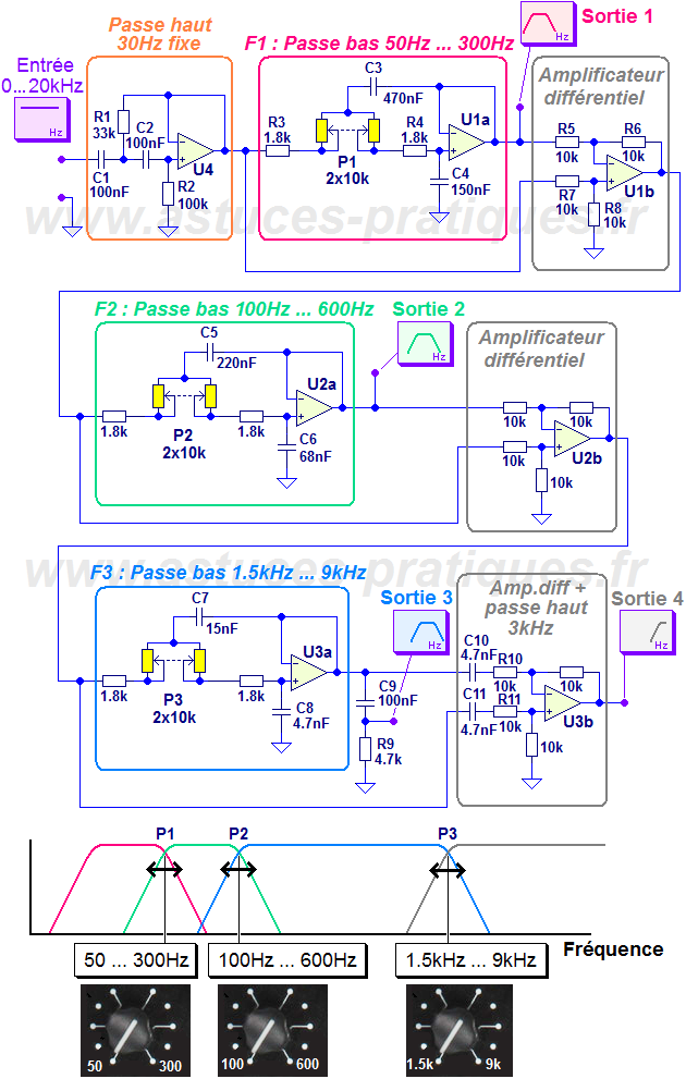
Here is the diagram of the active filter whose 3 transition frequencies are adjustable:

Active filter diagram for 4-channel sound system (adjustable frequencies)
Characteristics of the active sound filter
Here was chosen a 4-way active filter with characteristics:
- channel 1: from 30Hz (fixed) to 50Hz ... 300Hz adjustable by P1 (infrared for subwoofer) - channel 2: from 50Hz ... 300Hz adjustable by P1 to 100Hz ... 600Hz adjustable by P2- channel 3: from 100Hz ... 600Hz adjustable by P2 at 1500Hz ... 9000Hz adjustable by P3- channel 4: from 1500Hz ... 9000Hz adjustable by P3 to 20000Hz and more
The high pass filter (orange box) is optional but highly recommended to protect the subwoofers from frequencies that are too low for them to reproduce. It is a 2nd order filter that gives an attenuation of -12dB / octave. This channel is intended for subwoofers, ideally based on speakers 46cm (18 inches) or at least 38cm (15 inches). The subwoofers are often laminar vent or better, toboggan or W-bin type.
Channel 2 will only provide a signal when P1 and P2 are in compatible positions, for example P1 adjusted for 100Hz and P2 adjusted to 250Hz. Transition frequencies are used to adjust channel 2 in a wide range of frequency bands.
Channel 4 does not have a low pass filter.
Operating principle of the active sound filter
The audio signal containing all the frequencies first arrives on the high frequency filter set at 30Hz. Its purpose is to eliminate frequencies below 30Hz to protect speakers from subwoofers or subwoofers ("infra"). This is a 2nd order filter based on the U4 op amp. For the sake of simplicity, C1 and C2 are chosen identical. The frequency response around the cutoff frequency is determined by the damping of the filter (related to R1 and R2, or more exactly to the square root of the ratio R1 / R2).
The signal coming out of U4 is now cleaned of the lowest frequencies and therefore contains frequencies from 30Hz to 20kHz. The limit of 20kHz is arbitrary and in fact only depends on the audio signal at the input of the filter.
The first low-pass filter (magenta box F1) is a low-pass filter of order 2 adjustable cut-off frequency from 50Hz to 300Hz approximately thanks to P1. When P1 is at its maximum value, the cutoff frequency is 50Hz. When P1 is at its minimum value, only R3 and R4 remain and the cutoff frequency is then 300Hz. The potentiometer P1 is a 10kOhms and must imperatively be double (stereo). The damping of the filter of order 2 is equal to the square root of the ratio C4 / C3. This equality is valid because we have chosen the two equal resistors R3 + P2 and R4 + P2. At the end of this low pass filter F1, we therefore have channel 1 of the filter: fixed cutoff at 30Hz and high cutoff of 50Hz at 300Hz depending on the position of P1.
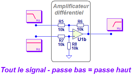
Remains the high pass filter whose cutoff frequency must be the same as that of the low pass F1 to avoid overlap between two channels or, conversely, a gap between the two channels. It is therefore necessary that the filter passes high lets pass all the frequencies that have not passed in the low pass. To do this cleverly, we can make the difference (subtraction) between the signal before low pass filtering and the same signal after low pass filtering.
When the filter low pass passes the signal, this difference is zero. When the low pass filter blocks the signal, the difference is equal to the signal. To realize this mathematical subtraction, one uses the differential amplifier assembly (gray box) which carries out the operation:
output = signal before low pass filtering - signal after low pass filtering
So the trick is this schema:

Active filter diagram passes high: suppression of the low frequencies to the signal which contains all
As a result, the output of the differential amplification is a high pass filter. We find the frequencies that have been blocked by the F1 low pass filter. This is the trick to route frequencies without losing or finding on both ways!
Note: it is easy to make an active low-pass filter of order 2 with a double (stereo) potentiometer in a Sallen Key structure, whereas it is not possible to realize a second order high-pass filter with a potentiometer double if we want a depreciation of the order of 0.5 to 0.7. In fact, to make an adjustable high frequency pass, there is no solution as simple as for the low pass.
In practice, one chooses R5 = R6 = R7 = R8 to realize a simple subtraction in the differential amplifier. The value of 10kOhms is arbitrary (we could have chosen 22k or 47k).
It is possible to stop the diagram at this level if you only want a 2-way active filter:
- from 30Hz (fixed) to 50Hz ... 300Hz (adjustable) - from 50Hz ... 300Hz (adjustable) to 20kHz
The output of the differential amplifier can constitute the treble channel for a satellite in a satellite system 2.1 + subwoofer.
But as here, we want a 4-way active filter, we use this output of the differential amplifier to redivize it in terms of frequencies. The operation is repeated with the low pass filter F2 (which gives the output 2) and the differential amplifier which is on its right.
Similarly for the filter F3. To better smooth the frequency response of the output 3, a simple filter based on R9 and C9 was added. This is an additional improvement that was found by empirical testing on a LTSpice IV simulation of complete editing.
Channel 4 (the treble channel) comes from the latest differential amplifier based on U3b.
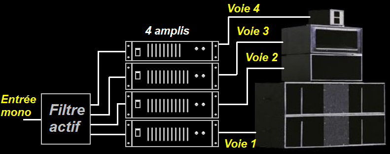
The purpose of the active filter is a sound system configuration of this kind:

Typical example of a system that requires a 4-way active filter
The amps for channels 1 and 2 must be the most powerful (there is more power in the bass than in the treble)
For the practical realization of the active filter
It is recommended to insert in series with the outputs of the op amps a resistor of 100 Ohms to avoid possible oscillations of the amps because of the parasitic capacitance between the hot point and the mass of the cables
The amps can be chosen quite freely. Here, the choice fell on the very classic and economical TL072.
The power supply is about +/- 12V and must be regulated, especially on the negative power supply (-Vcc). If one really wants to do without a voltage regulator (zener + transistor, 7812 or LM317), one can make two stages of capacitors separated by a resistance of 47 Ohms.
If it is desired to make a single printed circuit supply + active filter, it is necessary to avoid humming due to ripple current passages in the capacitors. The routing of the mass must make a separation between the ground tracks where the charging / discharging currents flow in the supply capacitors and the audio ground. We can of course make two different cards.
The adjustment potentiometers of the transition frequencies have interest to be linear for better ergonomics (to avoid that a quarter of the rotation of the potentiometer makes already almost all the variation).
Last word
This active 4-way filter is ideal for a high-powered sound system (4 separate amplifiers for a mono system). Variations can be made with only two or three channels.
If one wishes to realize a stereo system, it is necessary to duplicate the assembly. However the bass is not stereo and a mono output mixer will suffice for the left boxes and right boxes.


Post a Comment